
SD card - wiring and communication
6.6.2018
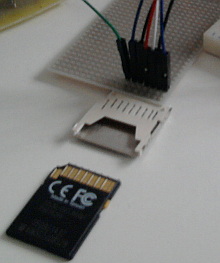
The card communicates using the SPI bus. In the picture below you can see the card slot with 7 wires which are - ChipSelect (CS), DataIn (DI), Ground, Power 3.3 V, SerialCLocK (SCLK), Ground, DataOut (DO).
I use the PIC18F24J50 MCU that is set to work at 8 MHz.
SPI settings:
//remappable pins settings
EECON2=0x55;
EECON2=0xAA;
PPSCONbits.IOLOCK=0;
RPINR21=0b00000110;  //SDI2 -> RP6 (RB3)
RPINR22=0b00000101;  //SCK2in -> RP5 (RB2)
RPOR4=0b00001001;    //SDO2 -> RP4 (RB1) (function number 9)
RPOR5=0b00001010;    //SCK2out -> RP5 (RB2) (function number 10)
EECON2=0x55;
EECON2=0xAA;
PPSCONbits.IOLOCK=1;

//SPI settings (module 2)
TRISBbits.TRISB1=0;
TRISBbits.TRISB2=0;
TRISBbits.TRISB3=1;
SSP2STATbits.SMP=1;
SSP2STATbits.CKE=0;
SSP2CON1bits.CKP=1;
SSP2CON1bits.SSPM=0b0010;
SSP2CON1bits.SSPEN=1;
SPI reading and writing functions:
BYTE status;

void spiWriteSD(BYTE data)
{
  SSP2BUF=data;
  while (!SSP2STATbits.BF)
    ;
  status=SSP2BUF;
}

BYTE spiReadSD(void)
{
  spiWriteSD(0xFF);
  return(status);
}
We will send informative data over the serial line. The UART registers have to be set:
//UART1 settings
TRISCbits.TRISC6=0;
SPBRG1=12;  //12.02 -> 38400
TXSTA1bits.BRGH=0;
BAUDCON1bits.BRG16=1;
TXSTA1bits.SYNC=0;
RCSTA1bits.SPEN=1;
TXSTA1bits.TX9=0;
TXSTA1bits.TXEN=1;
The text string sending function:
void sendSerialString(char *s)
{
  while ((*s)!='\0')
  {
    TXREG1=*(s++);
    while (!TRMT1)
      ;
  }
}
The card communication consists of several parts. The first of them is the initialisation part when the card is forced to work in SPI mode and the basic card parameters of the card such as working voltage range are retrieved. Then the card is ready to respond to the read and write commands.
The commands have the form of 6 bytes. The first byte is the command number, the next 4 bytes represent the data sent to the card such as the memory address, and the last byte is the CRC (Cyclic Redundancy Check).
We will be sending commands to the card with the following function:
BYTE status;

BYTE sendCommandSD(BYTE cmd,unsigned long arg)
{
  spiWriteSD(0xFF);

  spiWriteSD(cmd|0x40);

  spiWriteSD((BYTE) (arg››24));
  spiWriteSD((BYTE) (arg››16));
  spiWriteSD((BYTE) (arg››8));
  spiWriteSD((BYTE) arg);

  BYTE crc=0xFF;
  switch (cmd)
  {
    case CMD0:crc=0x95;break;
    case CMD8:crc=0x87;break;
  }

  spiWriteSD(crc);

  while ((status=spiReadSD()) & 0x80)
    ;

  return status;
}
The first byte sent is the dummy byte. The next one is the command number with the highest two bits set to '01'. The four bytes of the command argument follow - MSB first. The last byte - CRC - must be only valid in the initial phase of the communication. When the SPI mode is active the card is not checking whether the CRC is valid unless we explicitly demand it so the arbitrary value can be sent. There are fixed CRC values for the commands number 0 and 8 and in all other cases the value of 0xFF is sent.
After the last byte has been sent we wait for the one byte response with the highest bit set to zero. The remaining bits hold the card state information.
The following function sends the command number 55 with zero argument first and then the requested command.
BYTE sendACommandSD(BYTE cmd,unsigned long arg)
{
  sendCommandSD(CMD55,0);
  return(sendCommandSD(cmd,arg));
}